Load Cells : explained
Load cells systems for tanks, weighing hoppers
Industrial weighing scales for tanks, weighing hoppers
Do you have a question, a remark ? Please contact the author at admin@powderprocess.net| Section summary |
|---|
| 1. What is a load cell ? How it works ? |
| 2. What are the different types of load cells ? |
| 3. Load Cells accuracy |
| 4. Load Cells calibration |
| 5. Important points |
| 6. Buying load cells : Load cells
manufacturers |
This page explores the different types and design of load cells that can be used in process industries.
1. What is a load cell ? How it works ?
Load cells are instruments that can convert a force exerted on them (for example by a tank, or hopper) into an electric signal. The more the force (weight) is important, the higher is the electrical signal produced. A properly calibrated controller can then translate the electrical current into a weight unit understandable by the user.
Load cells play a central role in many powder processes since they allow to measure the weight of solids processed. Load cells are used for Dosing purpose or mass balance recollection.
The proper specification, calibration and then maintenance of load cells systems is key to make sure the process will perform as designed, will produce within quality specifications and at a controlled cost.

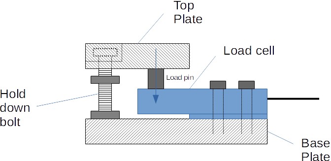
Figure 1 : Typical design and
installation of a load cell
2. What are the different types of load cells ?
Choosing a Load Cell by Type
There are different technology principles for load cells but most of them are strain gauge load cells which means that strain gauges are attached to the body of the load cell. When the body is deformed because of the force/weight applied by the equipment on which it is mounted, then the strain gauge deforms as well which has as an effect to change its resistance. It is then possible to measure it through the voltage and send a digital signal to a controller thanks to an analog to digital converter (for example HX711). The voltage is proportional to the deformation and thus to the force applied.
The different weighing principles for strain gauge load cells are summarized below :
Table 1 : The different principles of load cells
| Compression Load Cells (Load button) |
| Compression / Tension Load Cells |
| Bending Beam Load Cells |
| S Beam Load Cells |
| Single Point Shear Beam Load Cells Double Ended Shear Beam Load Cells |
| Ring torsion Load Cells |
| Canister Load Cells |
It also exist piezoelectric load cells that do not use strain gauges, but rather a piezoelectric material which is generating a voltage depending on the force it is submitted to.
Industrial load cells can be installed at many places in bulk solids processes. Common equipment are tanks and hoppers scales used for dosing purpose (weighing hopper on load cells) or to have an idea of the stock of product at a given moment (tanks or silos on load cells).
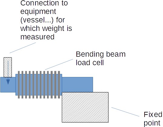
Bending beam load cells are very often used to measure the weight of hoppers :

Figure 2 : Bending beam load cell
Another choice for a similar application can be tension /compression
load cells (pancake load cells) :

Figure 3 : Tension Compression (pancake type) load cell
Top
5 Most Popular
1.
Pneumatic transport design guide
2. Ribbon
blenders
3. Powder mixing
4. Hoppers design guide
5. Measuring degree of
mixing
Top 5 New
1. Continuous Dry Mixing
2. Mixing speed
3. Mixer cycle time
optimization
4. Batch
/ continuous mixing comparison
5. Energy Savings
3. Load cells accuracy : How accurate are load cells ?
In order to have a good and reliable measurement, it is 1st necessary to select the load cells sensors regarding the load cells measuring range and the overload that may be applied to the load cells during their operation.
The process operator must determine what is the measuring range that will constitute the normal operating conditions of the load cells and for which he requires a certain accuracy. This range will define the load cells measuring range. From this range, different safety factors need to be taken to prevent damage of the load cells by overload.
The values given below constitute a general approach, an assessment must be done to check if the load cells will not encounter higher loads after installation (during some maintenance operations for example).
Table 2 : Load Cells Capacity definitions
| Capacity variable | Definition |
|---|---|
| Load Cell Measuring range | Range for which the reading should be within the maximum
permissible error This is the expected weight to be measured by the process (example the max weight to be dosed for a recipe) |
| Safe Load Limit | Max load that can be applied to the load cells without
causing damage. Rule of thumb : 150% of Measuring range |
| Ultimate load | Max load that can be applied without leading to physical
damage. Accuracy may however be impacted if such loads are
reached. Rule of thumb : 300% of Measuring range |
| Safe Side load | Max load that can be at 90 degree (on the side) without
causing damage. Rule of thumb : 100% of Measuring range |
Some manufacturers are also proposing tension modules. The load is then pulling on the load cell instead of pushing on it, like in most of the applications.
Events that can lead to overload include : shock loading, agitators in movement (dynamic load), off center load, overloading a scale.
Calculation formula should be applied to take into consideration the situation in which the load cell will be installed and then select the right load cells capacities.

Figure 4 : Capacities and loads - graphical representation
For an industrial process, in an industrial environment, an accuracy of 0.1% of the applied weight can be reached. Load Cells of high precision could reach around 0.03% of the rated capacity (max measuring range).
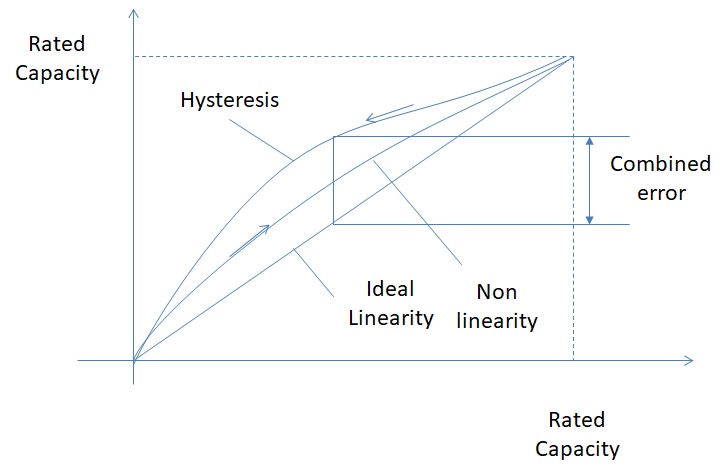
The error of the scale is the combinations of calibration, linearity, hysteresis and repeatability errors. It is possible to perform a calibration sequence so that the calibration sequence is reduced to around 0, as well repeatability errors should be very miniminal (less than 0.03% of Rated Capacity). In practice, the accuracy of the scale system will be equal to the combined error.
Combined error = Non linearity + Hysteresis = 0.02 to 0.03% of Rated Capacity. This is for 1 load cell.
All reading, from 0 kg to Rated Capacity, should be within the accuracy (Combined error * Rated Capacity * Number load cells). This means that at low load, the error (as % of the weight applied) should be higher than at high load.

Figure 5 : Load cells performance Graph
On top of this, the repeatability error, which should be very minimal, should be controlled after installation to make sure there is no issue.
Another important characteristic is the minimum verification interval (vmin). It is the minimum amount of mass that must be applied to the load cells without exceeding the max permissible error. It is to be related to the combined error which is expressed as % of the Rated Capacity. During design it must be checked that (vmin=Emax/gamma <h; minimum weight expected on the scale).
The resolution of the scale must also be defined. It is related to the number of digits the scale will display, although it is not directly related to the load cells accuracy (it is an illusion to ask more digits than the scales accuracy).
Summary : important load cell sensor characteristics to define when designing an installation
Table 3 : Definition of design values for load cells
| Design parameter | Definition |
|---|---|
| Combined error | The Combined error is giving the best precision one can expect from load cells properly calibrated. For individual load cells, it should be in the range of 0.03% of the Rated Capacity (Emax). As a consequence, accuracy should be expected better at high load than at low load |
| Minimum verification interval (vmin) | This is the minimum weight that must be applied to the load cells to stay in the design accuracy |
| Resolution | This is the number of digits that can be displayed by the load cells. It is not related to the accuracy. |
4. Load Cells Calibration verification
To perform load cells calibration, it is necessary to have a reference. This reference is usually provided by test weights that have been calibrated by recognized institutes.
It is then necessary to follow a procedure defined by the supplier in order to load the scale with defined mass, check and record reading, then correct potential errors. In certain situation, for very large scale, it may be necessary to fill the scale with water to perform the calibration.
The load cells need then to be checked with the following tests, to be done in the order below :
Table 4 : Definition of calibration tests for load cells
| Test | Definition |
|---|---|
| Friction test | The test is performed by adding and removing several time
the same weight to the scale. The display shown must be the same and should not change by more than 0.02% of the scale Rated Capacity The friction test will make sure that there is no deviation of the repeatability (explained above) due to some interactions of the environment with the load cells (the scale is in friction with another part for example) |
| Creep test | The test is performed by adding a weight on the scale and
waiting for a defined time. During the waiting time the reading should not change by more than 0.01% of the scale Rated Capacity The creep test will detect any tension that will relax due to the application of the weight (a tension to a flexible for example) |
| Linearity and Hysteresis (=Combined error) | Weight are added step by step on the scale, then removed.
Value read are compared to calibrated value of the weight. It will detect any deviation of linearity of histeresis that could be the sign of an incorrect calibration of the load cells or interaction of the environement with the scale It may not be possible to test the whole scale, in this case, a minimum of 10% of the Rated Capacity should at least be targetted |
The tests and reference values given above are general and recommendations of suppliers could vary. They are given as 1st indications and to perform sense check. The verification of suppliers specifications and manual should always be done. The 3 tests given above are the minimum to be performed, other tests may be requested by manufacturers, especially for precision feeders.
5. Important points
Installation of load cells
Load cells are very sensitive to current. A particularly important point is to ensure that load cells are electrically isolated if any welding work is on going close to the load cells. A good practice would be to install load cells once all welding works have been completed. If the load cells is not properly isolated or if the earthing of the welding station is not properly placed, leak currents can damage it.
Load Cells in Harsh Environments: Addressing Environmental
Challenges
In industrial processes, load cells often face challenging
environmental conditions that can impact their performance. Factors
such as temperature variations, humidity, and corrosive substances
can affect the accuracy and longevity of load cells. Engineers need
to consider these environmental challenges during the design and
installation phases to ensure the reliability of the weighing
system.
One key consideration is the sealing and protection of load cells
against dust, moisture, and harsh chemicals. Implementing proper
enclosures and protective measures, such as IP ratings, can
safeguard load cells from external elements. Additionally, engineers
should explore load cell models with enhanced environmental
resistance, specifically designed for applications in corrosive or
extreme conditions.
Regular maintenance routines should include checks on the integrity
of the protective measures and the overall condition of load cells.
Periodic inspections can help identify potential issues early on,
preventing system failures and ensuring accurate weight measurements
over the long term. In summary, addressing environmental challenges
is crucial for maintaining the accuracy and reliability of load
cells in industrial settings.
6. Buying load cells : Load cells manufacturers
It is important to rely on proven load cells sensors manufacturers in order to get a precise, reliable, and durable weighing system.
The reader can refer to the company GAROS (www.garos.fr) for information on load cells, expert advice and buying (note that PowderProcess.net has no link with this company).
Other possibilities are HBM load cells, OMEGA, load cells, FLINTEC load cells, Tedea-Huntleigh, Sensortronics, mettler toledo load cell, Vishay load cells, HARDY load cells (note that PowderProcess.net has no link with these companies).